In a solar electric boat, the battery is not a passive box that stores whatever energy happens to arrive; it is the core energy system that sets hard boundaries on what the vessel can actually do on water. Range, speed, passenger capacity, schedule reliability, and even the business case all sit inside the envelope defined by the battery and how it is integrated into the boat.
1. “More than Storage”
On diesel boats, designers and operators focus on engine power and fuel tanks—as long as fuel suffices, power flows on demand without storage-imposed limits. Solar electric boats invert this logic: the battery emerges as the core constraint, with motors sized to match its safe, economic delivery limits.
Diesel boats rely on a straightforward energy chain: fuel tank (storage), diesel (energy source), and engine (power converter). The tank can often be scaled up with minimal cost or weight penalties, allowing operators to extend range by simply adding volume. Fuel flows freely to the engine, which then delivers power on demand without strict limits from the storage itself.
Batteries impose dual constraints—both energy capacity (total kWh available, like fuel volume) and power capability (maximum kW deliverable, akin to fuel pump and pipe size). Scaling energy requires exponentially higher costs, weight, and volume due to cell stacking, cooling, and safety systems, unlike enlarging a tank. Power limits emerge from C-rate (discharge speed), internal resistance, and thermal management, capping peak motor output even if energy remains.
The battery’s role extends to every operational and design aspect of a solar electric boat, creating tight interdependencies unlike the more forgiving diesel.
1.1. Speed and Range Impact
For a given hull, required propulsion power rises sharply with speed; in many displacement boats, power can scale roughly with the cube of speed. This makes range and speed tightly coupled to the battery. A small increase in scheduled cruising speed can demand a disproportionately larger battery if route length and headway are held constant.
Energy capacity (kWh) determines total distance between charges, but usable range shrinks with depth of discharge (DoD) limits to preserve lifespan—often 80% max for lithium packs. Solar input extends effective range as a buffer, yet intermittent weather forces conservative sizing to avoid operational changes.
1.2. Speed and Maneuvering Impact
Battery power density and maximum discharge rate (C-rate) set the ceiling for propulsion power, directly limiting top speed and acceleration. High C-rates enable quick maneuvers in currents or docking, but demand robust cooling and safety systems; insufficient power strands the boat during peaks, even with ample energy stored.
1.3. Payload and Capacity Impact
Batteries are heavy and occupy volume. Marine batteries for ferries and workboats often weigh several tonnes and take substantial space in machinery rooms or dedicated battery compartments.
- That mass counts directly against payload if draft, stability, or regulatory limits constrain displacement.
- Volume used for batteries is volume not available for passengers, cargo, or amenities.
Well-designed electric ferries place the battery low and centrally to minimise impact on capacity and trim while ensuring safe access for inspection and maintenance.
1.4. Trim and Stability Impact
Because batteries are dense and frequently mounted low, they can improve stability compared with equivalent fuel mass higher up or distributed differently. However, poor placement can create undesirable trim or roll characteristics:
- Concentrating batteries too far forward or aft can lead to bow down or stern down trim, increasing resistance and spray and reducing comfort or affecting planing.
- Asymmetric placement can introduce list or sensitivity to loading, complicating operations.
The naval architect’s weight and stability calculations must therefore treat the battery as a major structural weight, not an “equipment” afterthought.
1.5. Economics and Business Case Impact
Battery choice and sizing directly affect the total cost of ownership:
- Capital cost: Battery packs are still expensive, often dominating propulsion CAPEX (30-50%).
- Operating cost: Battery efficiency, cycle life and allowable depth of discharge influence how much energy must be bought from the grid and how often packs need replacement (7-10 years).
- Revenue: Range and speed limitations affect how many trips per day can be run, which in turn drives ticket or freight revenue.
Studies of electric ferries and hybrid offshore vessels show that correct battery dimensioning, combined with an appropriate duty cycle, can significantly cut energy cost and emissions compared with conventional vessels, but only when battery life and replacement cost are realistically accounted for. Under estimating degradation or overselling achievable speed is one of the fastest ways to undermine confidence in electric boats.
2. Why Marine Batteries Differ from Automotive Batteries
The success of electric cars leads many people to assume that marine batteries are essentially the same as automotive packs mounted in a hull. The underlying cell chemistries may be similar, but the requirements and risk profile are not.
2.1. Duty Cycle and Throughput
A commercial ferry or workboat may operate 8–16 hours per day, cycling a significant fraction of its battery capacity repeatedly, often 300 or more days per year.
Car batteries experience more variable and often gentler patterns: a mix of city and highway driving, nights at rest, and generally less predictable but lower annual energy throughput per vehicle.
Maritime analyses show that the typical duty cycles of large battery systems on ships are distinct from land EVs, with higher daily throughput and stricter reliability requirements. Cycle life at realistic depth of discharge becomes central to economics.
2.2. Environment and Mechanical Stress
Marine battery systems live in a harsher environment than most road vehicles:
- Constant vibration from engines or waves.
- Shock loads from slamming or impact.
- High humidity and salt laden air promoting corrosion and leakage currents.
- Limited cooling options in enclosed compartments.
These factors demand robust mechanical support, sealed enclosures with appropriate IP ratings, and careful routing of cables and ventilation. Many general purpose lithium packs are not suitable for long-term marine use without redesign.
2.3. Safety and Evacuation
Safety requirements and failure consequences differ substantially:
- On a road, a vehicle can often stop and occupants can evacuate quickly; external firefighting and emergency services are usually nearby.
- On water, evacuation is slower and more complex, and external assistance may be far away. A fire or gas event in a confined battery room can rapidly compromise the vessel.[ https://www.yachtingworld.com/all-latest-posts/lithium-battery-fires-the-10-point-safety-checklist-every-boat-owner-needs-160875]
This is why class societies and insurers increasingly recommend or require LiFePO₄ (LFP) chemistry for marine applications due to its superior thermal stability, and insist on marine grade BMS and installation practices rather than repurposed automotive solutions. [ https://www.nautilusinsurance.com.au/news/lithium-ion-battery-safety/]
In short, while automotive developments have driven down costs and improved performance, marine batteries must be designed and certified for the marine environment, not simply imported from road vehicles.
3. Key Concepts for Designers and Operators
A handful of basic concepts appear throughout the rest of this chapter and the book. Understanding them in practical terms helps designers, owners and regulators speak the same language.
3.1. Energy (kWh) vs Power (kW)
Energy, measured in kilowatt hours (kWh), is how much work the battery can do in total—how many “litres of fuel” you have in electrical form.
Power, measured in kilowatts (kW), is how fast that energy can be delivered—how quickly you can accelerate, climb a wave, or fight a current.
A 200 kWh battery driving a 100 kW propulsion system, in theory, could deliver full power for two hours, but real operation must account for efficiency losses, reserve margins and limits on depth of discharge.
3.2. State of Charge (SOC) and State of Health (SOH)
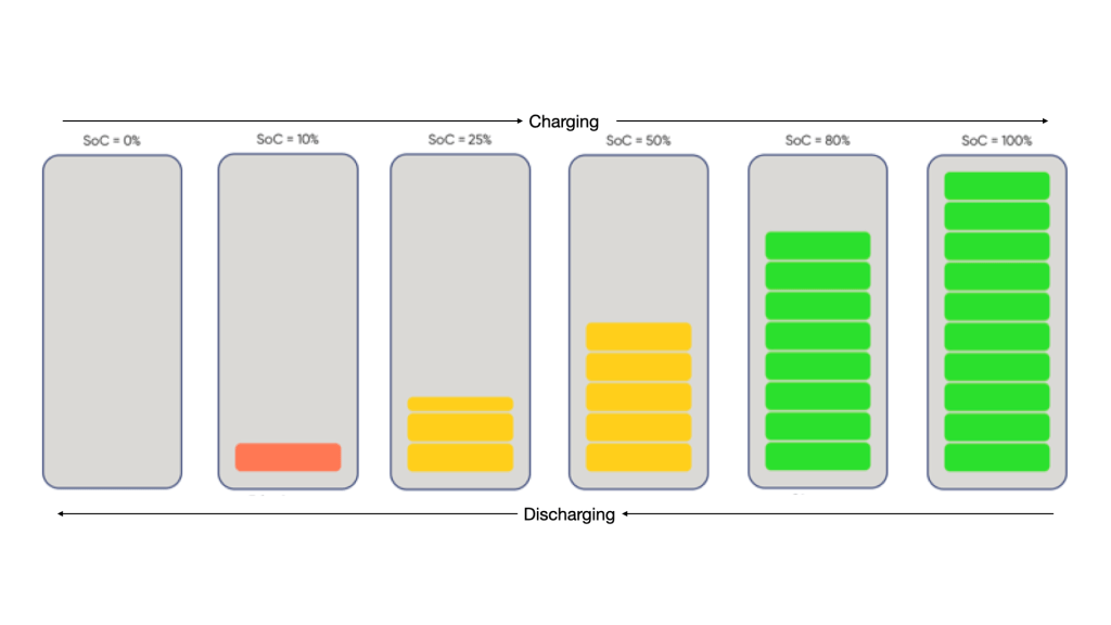
SOC acts as the battery’s real-time fuel gauge, showing available capacity as a percentage of maximum—operators rely on it to plan trips, avoid deep discharges, and time recharges from shore or solar input. Accurate SOC prevents stranding mid-voyage, especially in variable marine loads like currents or passenger surges.
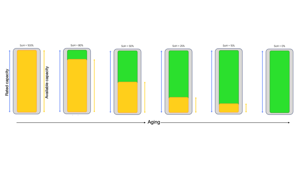
SOH quantifies battery aging by comparing current capacity to the original rated value, predicting remaining life for replacement scheduling and safety margins. Low SOH signals faster degradation from cycles or heat, critical for vessels where unexpected failure disrupts schedules.
Emerging data driven methods for SOH estimation on maritime batteries show how SOC, temperature, voltage and current time series can be used to track degradation and inform maintenance.
3.3. Depth of Discharge (DoD)
Depth of discharge describes how much of the battery’s nominal capacity is used in a cycle:
- Cycling between 80% and 30% state of charge corresponds to 50% DoD.
For many lithium chemistries, cycle life improves dramatically when operating within a moderate SOC window rather than using the full range on every cycle. Marine designers typically choose an operating window that balances usable energy with long life, often leaving top and bottom buffers.
3.4. Calendar Life vs Cycle Life
- Cycle life is the number of charge–discharge cycles until usable capacity falls to a set threshold (often 70–80% of original).
- Calendar life is how long the battery lasts simply as time passes, even if it is lightly used.
In a commercial boat, both matter: daily cycling consumes cycle life, while environmental exposure and resting conditions consume calendar life. Project feasibility depends on the earlier of these two constraints.
3.5. Round Trip Efficiency
Round trip efficiency is the fraction of energy put into the battery that can be retrieved later as useful output:
- High quality lithium systems often reach 90–95% round trip efficiency.
Higher efficiency means less energy lost as heat, lower operating cost, and reduced cooling burden. On solar electric boats, good efficiency helps capture more of the limited solar resource and reduces grid energy draw.
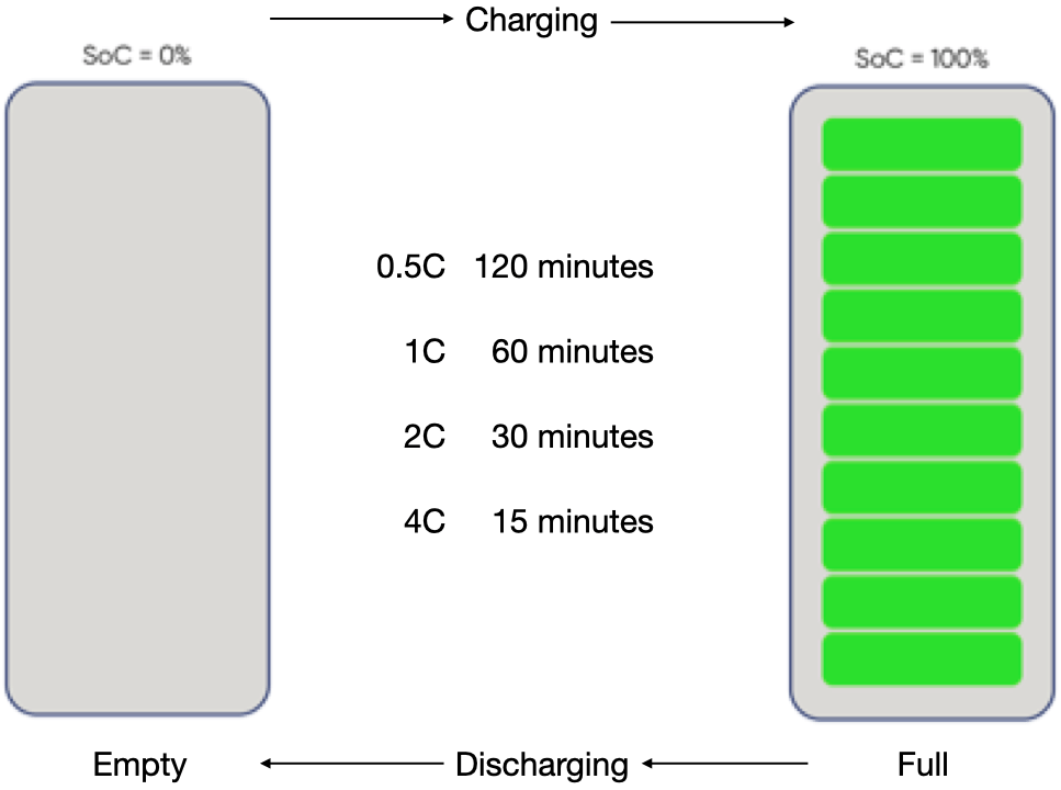
3.6. C Rate
C rate expresses charge and discharge current relative to battery capacity:
- 0.5C would take two hours (0.5 times of full capacity in one hour)
- 1C charging or discharging full battery will take one hour
- 2C only half an hour (two times of full capacity in one hour)
- 4C only 15 minutes (four times of full capacity in one hour)
High C rates produce more heat and accelerate degradation, while low C rates are gentler but may not deliver required performance or turnaround time. Many solar electric boats can be designed to operate at relatively low C rates during cruise and moderate C rates during manoeuvres and docking
3.7. Gravimetric and Volumetric Energy Density
- Gravimetric energy density (Wh/kg) indicates how much energy is stored per unit mass.
- Volumetric energy density (Wh/L) measures energy per unit volume.
Small boats are sensitive to both: too much mass affects displacement and fuel savings; too much volume displaces payload or usable space. Designing with realistic energy densities, including packaging and structural mass, prevents disappointment when moving from data sheet numbers to real installations. On larger boats the sensitivity to mass and volume is less.
3.8. Thermal Stability
Thermal stability describes how a battery chemistry behaves under abuse or fault.
Chemistries like LFP have markedly better thermal stability and a lower tendency to propagate thermal runaway than high nickel NMC/NCA cells, which is why insurers and yacht regulators increasingly recommend LFP as the “gold standard” for marine safety.
On a vessel, where escape options are limited and a single fire can be catastrophic, thermal stability becomes a primary selection criterion, not just a safety margin.
4. Battery Chemistries Used in Electric Boats
Over the years, several battery chemistries have been used in electric boats, each reflecting the technological maturity, cost structures, and operational understanding of its time. While all rechargeable batteries rely on reversible electrochemical reactions to store and release energy, their real-world suitability for marine applications depends on far more than laboratory performance figures.
In solar electric boats, batteries are subjected to daily cycling, partial charging, long dwell times at high state of charge, and installation in confined, often poorly ventilated spaces. Unlike electric road vehicles, which experience short bursts of high power followed by long idle periods, electric boats typically operate for extended durations at steady loads. As a result, battery chemistry selection must carefully balance energy density, usable depth of discharge, cycle life, safety, thermal stability, and lifecycle cost, rather than peak power capability alone.
4.1. Lead-Acid Batteries
Lead-acid batteries were the earliest energy storage systems adopted for electric boats and were, for many years, the default choice due to their low upfront cost, wide availability, and long history in marine and automotive applications. Variants include flooded lead-acid, absorbed glass mat (AGM), and gel batteries, each offering incremental improvements in maintenance requirements and leakage resistance.
Electrochemically, lead-acid batteries rely on the reversible conversion of lead dioxide and sponge lead into lead sulphate during discharge. While this chemistry is robust and tolerant of abuse, it is fundamentally constrained by low gravimetric and volumetric energy density. In marine applications, this translates into extremely heavy battery banks to achieve even modest operational range.
In practice, only about 50% of the nominal capacity of a lead-acid battery can be used regularly without severely reducing its lifespan. Repeated deep discharges accelerate sulphation, an irreversible process that reduces active material availability and internal conductivity. This limitation is particularly problematic in solar electric boats, where daily cycling and variable solar charging are inherent to normal operation.
Maintenance requirements further reduce their suitability. Flooded lead-acid batteries require regular electrolyte topping, ventilation to prevent hydrogen accumulation, and careful charge control. AGM and gel batteries eliminate some maintenance concerns but remain sensitive to deep cycling and elevated temperatures. From a naval architecture perspective, the excessive weight of lead-acid banks negatively impacts vessel efficiency, payload capacity, and stability margins.
As a result, lead-acid batteries are now largely obsolete for commercial solar electric boats and ferries, though they may still be found in small recreational craft, auxiliary systems, or legacy installations where capital cost is the overriding constraint.
4.2. Lithium-Ion Batteries – An Overview
The term lithium-ion battery refers to a broad family of chemistries that share lithium ions as the charge carrier but differ significantly in cathode and anode materials. These differences strongly influence energy density, thermal behavior, cycle life, degradation mechanisms, and safety characteristics.
Compared to lead-acid batteries, lithium-ion systems offer much higher energy density, greater usable depth of discharge (typically 80–90%), and significantly longer cycle life. These advantages enable lighter vessels, improved hydrodynamic efficiency, and greater design flexibility in solar electric boats.
However, lithium-ion batteries also introduce new challenges. They are more sensitive to overcharge, over-discharge, and temperature extremes, necessitating reliable battery management systems (BMS). In marine environments—where batteries are installed close to passengers, crew, and critical systems—the intrinsic safety of the underlying chemistry becomes as important as the sophistication of electronic protection.
| NMC / NCA battery | LFP battery | LTO battery | |
| Cathode | NMC / NCA | LFP | LFP |
| Anode | Graphite | Graphite | LTO |
4.3. Nickel Manganese Cobalt (NMC) and Nickel Cobalt Aluminum (NCA)
Nickel manganese cobalt (NMC) and nickel cobalt aluminum (NCA) chemistries are widely used in electric vehicles due to their high energy density and strong power capability. These characteristics allow compact and lightweight battery packs, which are critical in automotive applications where range and acceleration are key performance metrics.
From an electrochemical standpoint, these chemistries achieve high energy density through nickel-rich cathodes, but this comes at the cost of reduced thermal stability. Under abusive conditions—such as overcharging, mechanical damage, or inadequate cooling—NMC and NCA cells are more prone to exothermic reactions that can lead to thermal runaway.
In marine applications, their advantages are less compelling. Solar electric boats typically operate at moderate and steady power levels, making high peak discharge capability largely unnecessary. At the same time, continuous daily cycling and prolonged operation at high state of charge accelerate degradation in NMC and NCA cells, shortening effective service life.
To meet acceptable safety standards, these chemistries require robust BMS, active thermal management, and careful installation design, all of which increase system complexity and cost. Consequently, while NMC and NCA batteries may be used in high-performance or speed-oriented electric vessels, they are generally not well suited for mainstream commercial solar electric boats focused on reliability, longevity, and safety.
4.4. Lithium Iron Phosphate (LFP)
Lithium iron phosphate (LFP) batteries have emerged as the preferred chemistry for solar electric boats and electric ferries. Although their energy density is lower than that of NMC or NCA, LFP batteries offer exceptional thermal stability, long cycle life, and predictable degradation behavior.
The iron phosphate cathode forms a strong crystal structure that resists oxygen release at high temperatures, greatly reducing the risk of thermal runaway. This intrinsic stability is a major advantage in marine environments, where fire suppression and evacuation options are limited.
LFP batteries tolerate deep and frequent cycling exceptionally well, making them ideal for vessels that operate daily and rely on solar charging supplemented by shore power. They are also more tolerant of partial charging and extended periods at high state of charge—common operating conditions in solar electric boats.
From a lifecycle cost perspective, LFP batteries often outperform higher-energy-density alternatives. Their longer service life, lower degradation rates, and reduced thermal management requirements frequently offset the slightly higher initial cost per kilowatt-hour. For passenger vessels and workboats, these characteristics simplify system design, enhance safety, and ease compliance with marine certification requirements.
4.5. Lithium Titanate (LTO)
Lithium titanate (LTO) batteries represent a technically impressive but niche lithium-ion chemistry. By replacing the conventional graphite anode with lithium titanate, these batteries achieve extremely fast charge and discharge capability, outstanding low-temperature performance, and cycle life often exceeding 15,000–20,000 cycles.
LTO batteries can accept very high charge rates with minimal degradation, making them suitable for applications involving frequent short charging intervals. From a safety perspective, they are among the most stable lithium chemistries available.
However, these advantages come with significant trade-offs. LTO batteries have very low energy density, resulting in large and heavy battery systems for a given energy requirement. Their cost per kilowatt-hour is also substantially higher than LFP or NMC, limiting their economic viability.
In marine contexts, LTO chemistry may be appropriate for high-frequency ferries operating on fixed routes with fast charging infrastructure, where battery volume can be accommodated and rapid turnaround is critical. For solar-dominant electric boats, however, the low energy density and high cost generally make LTO an impractical choice.
5. Battery Pack Design for Marine Application
While battery chemistry defines the fundamental behavior of cells, it is the battery pack design that determines how safely and reliably those cells operate on a boat. Marine environments impose constraints that differ significantly from automotive or stationary applications, making pack-level design a critical engineering task.
A marine battery pack is composed of multiple cells arranged in series and parallel configurations to achieve the required voltage and capacity. Beyond electrical configuration, the physical arrangement of cells plays a vital role in thermal management, mechanical robustness, and fault containment. Continuous vibration, wave-induced shocks, and long operating hours demand mechanically secure mounting and robust interconnections.
Marine battery enclosures must provide protection against moisture, salt spray, and corrosion while allowing adequate ventilation or controlled venting. High ingress protection (IP) ratings are essential, but complete sealing without thermal consideration can be counterproductive. A well-designed enclosure balances environmental protection with heat dissipation and safety venting in the event of abnormal conditions.
Weight distribution is another unique marine consideration. Batteries are often the heaviest single system onboard, and their placement affects trim, stability, and structural loading. Poorly located battery packs can increase drag, reduce efficiency, and negatively impact passenger comfort. As a result, battery integration must be coordinated closely with hull design and naval architecture.
Redundancy and fault tolerance are increasingly important in commercial solar electric boats. Dividing energy storage into multiple independent battery strings or compartments allows continued operation in the event of a partial failure and enhances safety by limiting the consequences of a single fault.
6. Battery Safety in Solar Electric Boats
Battery safety is one of the most critical aspects of electric boat design, particularly for passenger vessels. Unlike land-based systems, marine environments impose unique constraints on evacuation, firefighting, and emergency response. A well-designed battery safety system must therefore address multiple layers of risk—from cell-level failures to system-wide fault isolation.
6.1. Thermal Runaway and Fire Risk
Thermal runaway occurs when a battery cell enters an uncontrolled overheating state, releasing energy rapidly and potentially causing fire or explosion. In confined marine spaces, such events can escalate quickly and are often difficult to manage using conventional firefighting methods.
The risk and severity of thermal runaway depend on battery chemistry, cell quality, environmental conditions, and system-level protections. Chemistries with higher thermal stability—such as LFP—significantly reduce the probability of catastrophic failure, but do not eliminate the need for careful engineering and operational control.
6.2. Battery Management System (BMS)
The Battery Management System is the operational brain of the battery pack. It monitors cell voltages, temperatures, and currents, ensuring safe operation across all conditions. The BMS provides protection against overcharging, over-discharging, short circuits, and thermal overload.
In marine applications, BMS reliability is more important than extracting maximum performance. Conservative thresholds, robust fault detection, redundancy, and seamless integration with the vessel control system greatly enhance both safety and operator confidence. In marine application water proofing (most marine BMS units are rated IP67) and vibration resistance are important.
BMS are of two types of configurations:
- Integrated (Drop-in): The BMS is inside the battery case. It is easy to install but has current limits (usually 100A–200A).
- External (Modular): The BMS sits outside the battery and controls an External Contactor (a heavy-duty relay). This is the “gold standard” for large boats or electric propulsion because it can handle 500A+ and allows you to disconnect charging and discharging separately.
High-end marine BMS units communicate via CAN bus or NMEA 2000. This allows you to see your battery’s State of Charge (SOC) and health directly on your MFD (Multi-Function Display)—the same screen you use for your solar plant, motors, GPS and fishfinder.
6.3. Fire Safety in Battery Systems for Solar Electric Boats
Fire safety must be approached as a layered system with three stages:
- Prevention – eliminate or minimise conditions that lead to failure
- Detection – identify abnormal behaviour at the earliest possible stage
- Mitigation – limit damage and prevent propagation if failure occurs
This hierarchy reflects a core design philosophy: the safest fire is the one that never occurs; the second safest is the one detected before it grows; mitigation is the final line of defence.
Unlike conventional fuel-based systems, battery-related fire risks arise from internal failures, electrical faults, or thermal stress rather than external ignition sources. Effective fire safety therefore depends on controlling operating conditions, identifying abnormal behaviour early, and limiting the consequences of failure.
6.4. Fire Prevention
Fire prevention focuses on avoiding conditions that can trigger battery failure. Prevention begins with appropriate chemistry selection, system design, and operational discipline.
At the battery level:
- Use thermally stable chemistries such as LFP for commercial/passenger vessels
- Define conservative limits for voltage, current, and temperature
- Avoid prolonged operation at extreme states of charge
The BMS plays a critical preventive role by continuously monitoring health parameters and enforcing safe operating envelopes.
From an installation standpoint, prevention also includes:
- Adequate ventilation to prevent heat and gas build-up
- Mechanical protection from vibration, shock, and water ingress
- Proper segregation from combustible materials
Operational prevention includes crew training, periodic inspection, and conservative charging strategies aligned with solar-dominant operation. Collectively, these measures significantly reduce failure probability.
6.5. Fire Detection
Even with strong preventive measures, failure cannot be eliminated completely. Early detection is therefore essential—especially in marine environments where response is constrained.
Battery-related failures typically progress through precursor stages such as internal heating or off-gassing before flames appear. A multi-layered detection system is most effective, combining:
Gas Detection
The earliest indicator of cell malfunction. Overheating or internal failure can release flammable and toxic gases such as hydrogen, CO, and volatile organic compounds. Gas sensors in battery compartments enable early shutdown, alarms, and ventilation activation—often before ignition occurs.
Heat/Temperature Detection
Independent heat detectors provide redundancy beyond the BMS and can identify external thermal abnormalities rapidly. Rate-of-rise and fixed-temperature detectors are particularly useful for catching thermal events before they escalate.
Smoke Detection
Smoke often appears later in the failure sequence, but sensitive or aspirating detectors can identify secondary fires or insulation breakdown. Detector placement must account for marine humidity, airflow, and vibration to minimise false alarms.
Detection systems must be integrated with vessel alarms and automated control responses to ensure timely crew action.
6.6. Fire Mitigation
Fire mitigation focuses on limiting the impact once abnormal conditions are detected. Both passive and active measures are essential, with strong emphasis on containment.
Key mitigation strategies include:
Thermal and Electrical Insulation
- Fire-resistant thermal barriers around modules to slow heat transfer
- Electrical insulation to prevent short circuits and arcing in humid or vibrating environments
Compartmentalisation
Battery rooms should be designed as fire-contained zones with insulated bulkheads, preventing heat or flame spread to occupied spaces. This is especially important for passenger vessels where safe evacuation routes must be preserved.
Additional mitigation actions include:
- Automatic isolation of affected modules or strings
- Immediate shutdown of charging/discharging
- Activation of ventilation or extraction systems to remove heat and gases
These measures help contain faults and prevent thermal propagation.
6.7. Fire Fighting
In larger vessels, mitigation measures may extend to dedicated fire suppression systems designed Firefighting is the last resort and must be approached with caution due to the unique behaviour of lithium-ion fires. Water can react with battery electrolytes, worsening the situation, so marine crews must use specialised procedures.
Appropriate Agents
- Class D extinguishers
- Dry chemical agents (e.g., sodium bicarbonate)
- Metal-fire foams
These should be applied from a safe distance.
Tactical Response
- Evacuate and isolate the area
- Cut electrical power immediately
- Prevent spread to adjacent compartments
- Ventilate gases such as HF that may be released
Larger vessels may include automatic CO₂ or aerosol suppression systems, but these should be seen as supplementary—not replacements for proper prevention and detection.
After extinguishing, continuous monitoring is essential because lithium-ion cells can re-ignite hours later.
6.8. Design Philosophy
Effective fire safety in solar electric boats depends on respecting the hierarchy:
Prevent → Detect → Mitigate → Fight
Prioritising passive safety—such as correct chemistry, insulation, and compartmentalisation—ensures measures remain effective even during power loss or system failure.
This layered design philosophy aligns with modern marine safety regulations and builds confidence among operators, regulators, insurers, and passengers.
Charging, Solar Integration, and Battery Life
Solar electric boats typically experience a charging profile very different from grid-connected electric vehicles. Solar charging is slow, continuous, and often partial, which can be beneficial for battery longevity when properly managed.
Frequent shallow cycling and partial state-of-charge operation reduce stress on many lithium-based chemistries. However, prolonged operation at very high or very low states of charge can accelerate degradation. Effective charge control strategies balance energy harvesting with battery health.
Thermal effects during charging are also important. Even slow charging generates heat, and inadequate ventilation can lead to elevated temperatures over long operating periods. System design must therefore consider cumulative thermal loads rather than peak values alone.
Marine Regulations and Certification
Battery systems in boats are subject to evolving regulatory frameworks that often lag behind technological development. Many standards originate from automotive or stationary applications and require adaptation to marine realities.
Marine certification focuses on risk reduction, fault containment, and passenger safety. Classification societies increasingly adopt risk-based approaches, evaluating system design, redundancy, installation practices, and emergency procedures rather than prescribing specific technologies.
Clear documentation, conservative design choices, and early engagement with regulators significantly improve the certification process and long-term operational acceptance.
Lifecycle, Degradation, and End-of-Life Considerations
Battery performance inevitably degrades over time due to chemical and mechanical processes. Capacity fade and increased internal resistance reduce usable energy and efficiency, eventually necessitating replacement.
For commercial solar electric boats, understanding degradation patterns is essential for financial planning. Batteries should be selected not only for initial performance but for predictable and gradual aging behavior.
Second-life applications, such as stationary energy storage, may extend the useful life of retired marine batteries. End-of-life recycling is equally important, both from an environmental perspective and to recover valuable materials. Developing robust recycling pathways is particularly relevant in regions where electric boat adoption is accelerating.
Design Trade-offs and Practical Recommendations
No battery system is universally optimal. Design decisions involve trade-offs between energy density, safety, cost, and longevity. For most solar electric boats, chemistries prioritizing thermal stability and cycle life offer the best balance.
LFP currently represents a practical and reliable choice for many applications, particularly passenger ferries and workboats operating daily. LTO is suitable for short range, high speed vessels that require frequent fast charging.
Alternative chemistries may be justified in specialized scenarios, but only with careful risk assessment and system-level safeguards.
Ultimately, successful battery integration depends on treating the battery as a core marine system rather than a replaceable component. Thoughtful chemistry selection, conservative design, and operational discipline together enable safe, efficient, and economically viable solar electric boats.
